These are my (somewhat messy) initial designs and plans for the project.
This mind-map shows every area of the spacecraft I have considered, with the branches leading to possible features for each of the parts or rooms.
As you can see at the very bottom, it reads "[Thunderbirds]". As I was asking for advise for this mind-map, I was reminded of the awesome television show I watched so fondly as a child, and I felt such a fool for not remembering it, or mentioning it in my specification.
The shows visionary creator Gerry Anderson died on Boxing Day.
I always intended to name the ship in his honour from as soon as I was reminded, but with this news I felt compelled to dedicate this project to his memory. The ship's name will be Anderson IR (Interplanetary Rescue).
Above is the initial layout of the ship's bridge. I have taken much inspiration from the bridges of the Star Trek franchise. I chose this layout as it would be both familiar to the audience and practical. The captain, slightly raised on a central platform, can receive information from as many directions as possible (the light arrows show roughly the flow of information).
As you can see, I have used a hexagonal shape to maximise efficiency and strength. The rest of the ship will be designed around this, creating a honeycomb of rooms (unless they become redundant, like perhaps in corridors).
This was my initial ship layout, based on the hexagonal design.
As you can see from my notes, I thought the essential systems (communications, navigation, life support and the evacuee quarters, along with the bridge) should be more central, or at least be more localised, so as to be further from engineering (and the ship's engines) so they would perhaps be able to detach if there was any problems with the engines, thus preserving life (as that is the ship's purpose).
At the very top of the basic initial layout I have noted "think in decks". Above is my first rough attempt to do so, but as you can see I was as yet unable to significantly separate the vital systems and the engines.
This was a quick sketch where I seemed to solve the problem of separating the aforementioned systems. I finally realised this is why Star Trek's Enterprise had been designed with its long 'neck', as it separated the main decks from the engineering decks, and furthermore the engines themselves.
You can also see the (unrealistically large) landing gear on each corner.
Here are my design sketches for the ship's landing gear. I started by designing the 'feet', making them as adjustable as possible, allowing the craft to land on varied and uneven terrain.
I added the treads (with their own adjustable suspension) so that two 'toes' would be able to lift slightly and automatically move each 'foot' should the landing surface become unstable. This would also allow the ship to crawl along, enabling it to approach rescue sites without taking off.
I added engines onto the legs so it would be VTOL capable, allowing for swifter approaches and departures in hot zones and negating the need for substantial wings.

Above was my first design for the ship's communications tower, with antenna on top for long-range radio transmissions and a large dish for satellite communications.
However, whilst conducting research into the area I found (as noted) that a hollow glass tube would do the job whilst staying radar invisible. This could be extended and retracted as needed to avoid damage.
These are my designs for the spacecraft's defences. Mainly automated and designed to be non-lethal, the system would track incoming missiles and, depending on the range and speed of the incoming target, fire either a long range rocket or deploy flares.
Since these sketches I have added a railgun system for the rockets' initial propulsion and firing on closer targets.

Above is a quick first design for the ATVs the crew could take closer to rescue sites. These would be extremely tough, so as to survive most anything nature might throw at it.
I think I may deviate from this 'all-in-one' design and go various vehicles capable of different tasks.


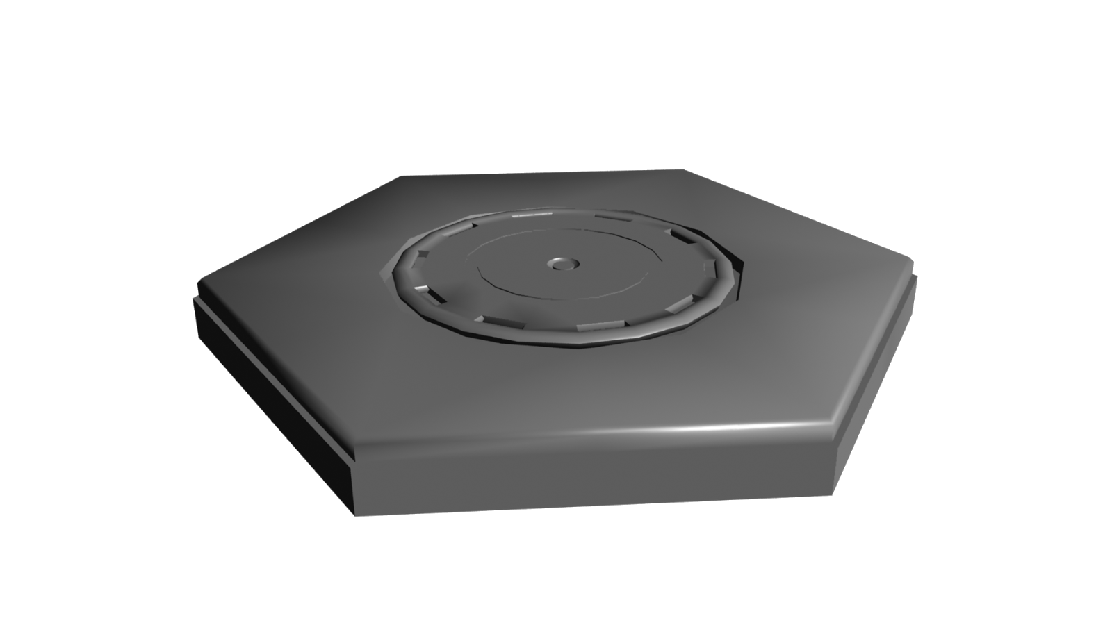


 (with Landing Gear)
 (with Arm)


 Stackable Kitchen Chair


